 After a long summer hiatus, I’m finally back working on the Solidoodle V2. Suffice to say it wasn’t ready to print right out of the box. Several issues were apparent – the bed was not level nor at the right gap from the tip, and there was a gouge out of the Kapton tape cover on the heated bed. Then I was bamboozled by an undocumented change to how the unit would get to the home position in addition to the reported temperature settings being 20C off of reality. These are all things one might not expect, but then again, getting an early unit from the start of production you have to be willing to work out some bugs.
After two firmware updates, bed leveling, replacing the Kapton sheet, and working on Skeinforge settings, I have my first successful print.
First Impressions
On the hardware side, the V2 is much better than the V1. The metal frame is well made, with crisp corners and solid construction. Actual threaded inserts are used instead of sheet metal screws into thin steel sheet. On the minus side, the electronics sit on the back side of the case with exposed wiring, and while this is low voltage, in the V1 the controller board was nicely isolated inside the case. I ordered mine with a heated bed which honestly could use a higher wattage heating element — it is slow to get to temperature, unlike the extruder.
Temperature Problems
OK basically if you set the temp of the extruder with Pronterface to 200C what you get at the tip is 218 – 220C! This is not good. Would somebody please save me the trouble of doing a thermistor calibration table for the firmware? If I set the extruder to 210C or whatever in the gcode file or from Pronterface, it should be 210C at the tip! (consider this a mild rant).
Parts not Sticking to the Build Platform
A huge issue. I spent a lot of time leveling, gap setting, and cleaning the Kapton. The build platform should be around 100C but mine never gets there. 85C is about all it can do, and then it has the issue of being wrong anyway with the thermistor calibration. I’ve not taken the time to measure the actual temperatures, but I did find an absolutely bullet-proof solution (pun intended). The 3D Systems Cube printer comes with “magic glue” to coat the aluminum build plate (there is no Kapton on it) and it washes off when done. Without a doubt this is some sort of PVA water-based glue [update: no, it is rather something like “Mucilage” of days gone by…] It is thick with a slightly amber color. It washes away with warm water in an instant, so it cleans off both the platform and part without a trace. Putting a thin layer on the Kapton surface, my prints have stuck with incredible success and are fairly easy to remove and clean!
Improvements
After hours of getting this to work for the first print, I’ll have to admit that at times I was ready to pack it up and send it back or unload it on ebay. I’m no stranger to these machines (as this blog should prove) but the lack of updated and machine-specific documentation, a serious temperature calibration issue (which could lead to hot-end meltdown), and some other quirks have proven to be frustrating. And, the first prints are still showing oozing and other issues that mean the Skeinforge profile needs tweaked. I’d like to see the electronics better protected. Some of the wiring cables appear to be too short and I’m worried that with more use they will break from fatigue.
I’m a big fan of competition in these sorts of things, and at the price it is a reasonable value if only the unit would live up to the results I got in the V1 right out of the box. BTW an excellent new blog on the V2 just went live in late August, so check out Ian Johnson’s Solidoodletips for lots of helpful material if you are looking to get your V2 set up.
Did I mention the Cube(tm) 3D printer? Yes, mine is working as I write this. A review will come next. How are the prints? Incredible right out of the box! 🙂
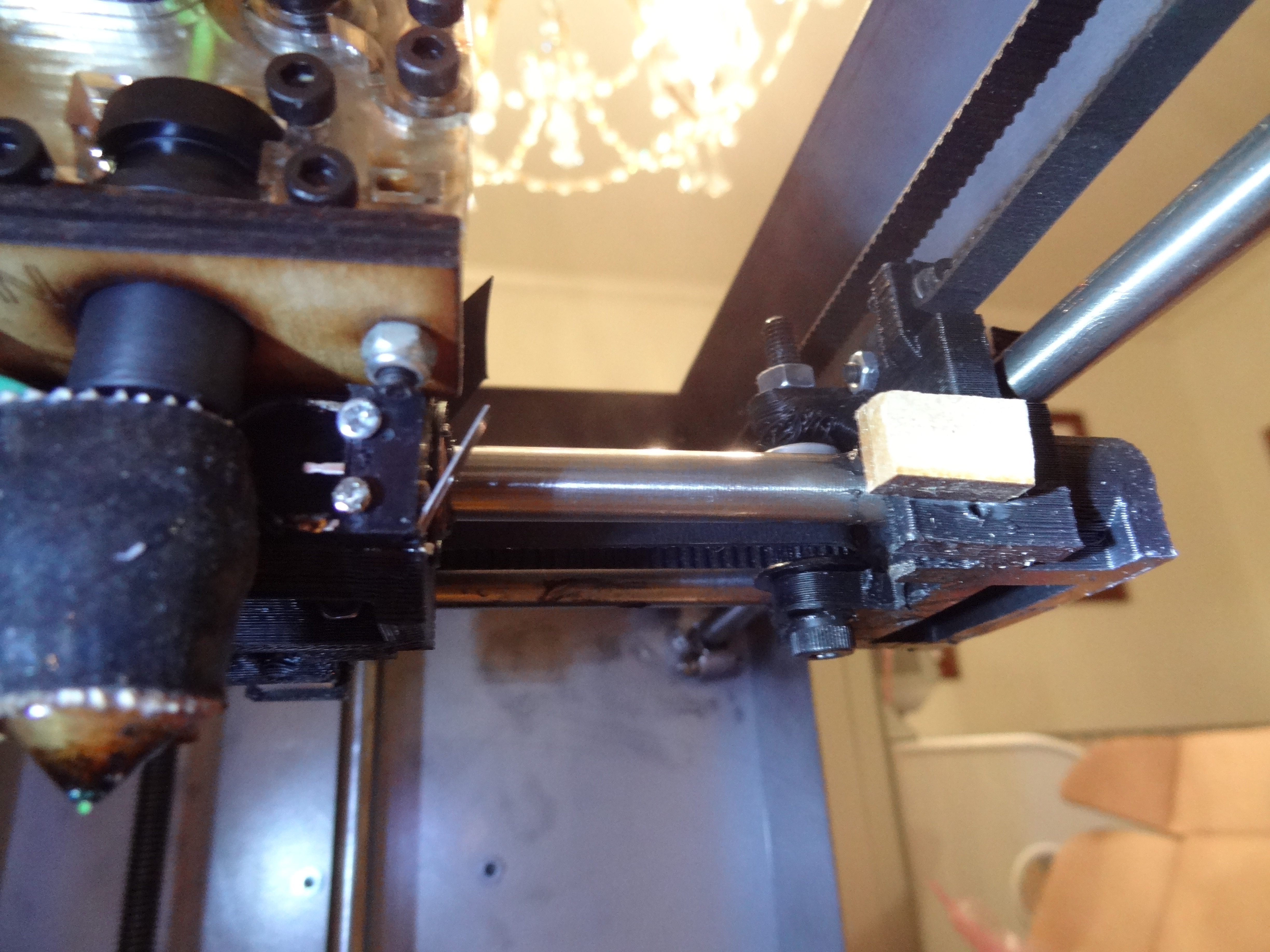
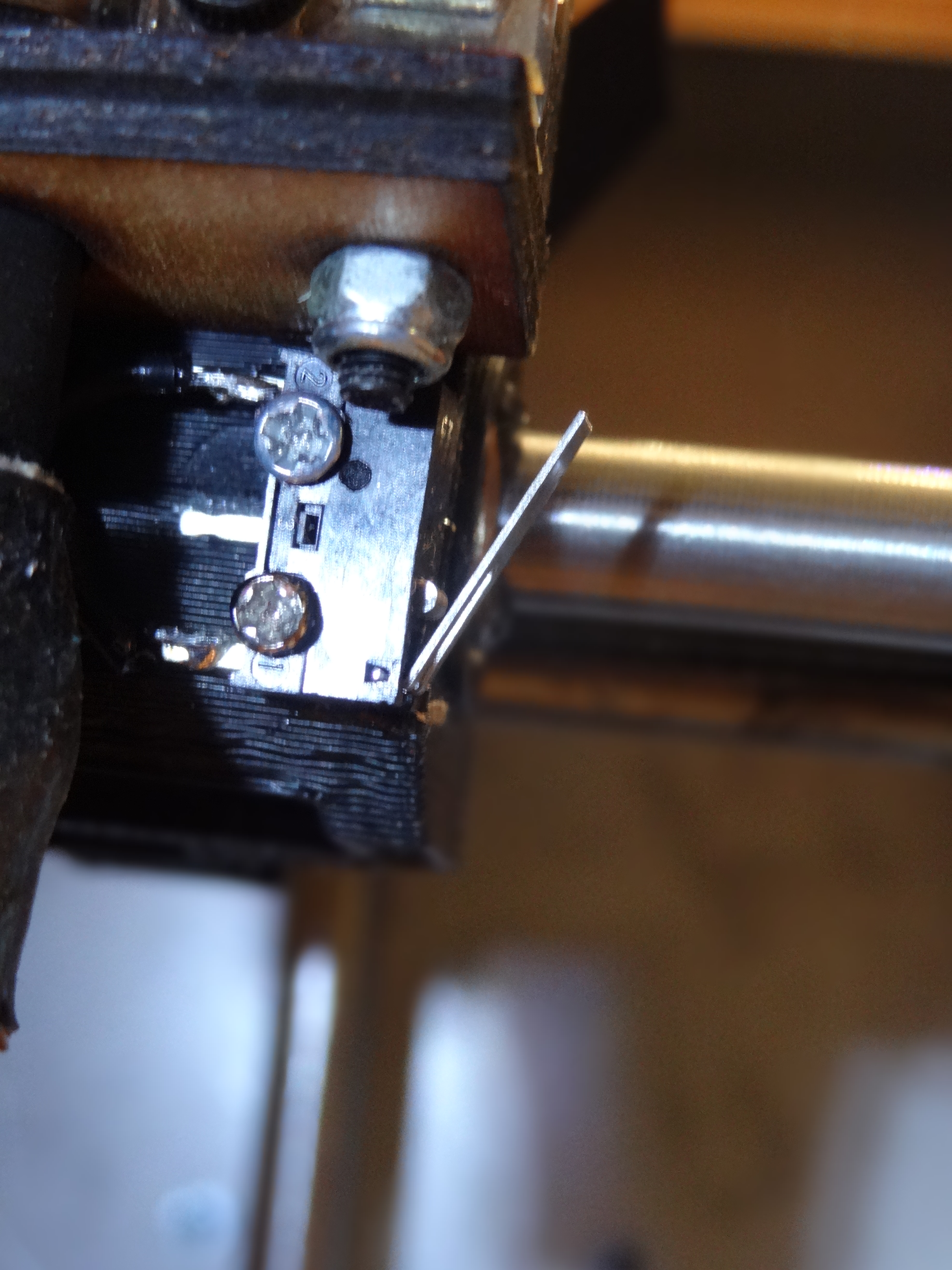
UPDATE: After trying to make a known size calibration cube, it became painfully obvious that something was wrong. The X and Y dimensions were well within specifications, but the Z was crunched by about 15%. I thought of all sorts of things, including the firmware calibration factor for the Z screw but that was not the problem. The Z axis motor driver was way too hot and the idle voltage was well over the .500 V the troubleshooting page suggests. This is how it came from the factory, so I made sure all of the stepper driver boards were adjusted to the suggested values, or slightly less, and now things are fully functional. I’ll put up some prints of parts soon. One change from the V1 to V2 for the Z axis is that the V2 uses a 5/16 threaded rod and the V1 used a 1/4″ Acme screw (which is far more precise). But, such is the need for cost savings.

 Although the signs of impending doom were evident since late last Fall, Solidoodle formally announced end of operations on March 28. You can read Sam Cervantes’ message to the Solidoodle community here: http://www.solidoodle.com/blog.html
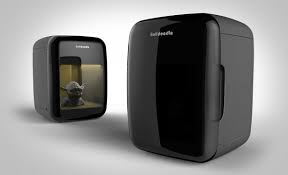


You must be logged in to post a comment.